Transformer wiring circuits starter 120v Grounding transformers 120v tapped 240v 480v sprinkler irrigation intermatic manuals timers rain 12v 2020cadillac vac tankbig
480v Transformer Wiring Diagram
480v to 120v 240v transformer wiring diagram Identifying terminals on 9070t industrial control power transformers Transformer wiring terminal instrument blocks modular reliable disconnect operation test easy current
Transformer power voltage stepdown
Transformer phase single voltage dual connections transformers parallel secondary connected electrical explained windings fig itsSquare d 75 kva transformer wiring diagram 480v transformer wiring diagramSingle phase transformer connections.
Transformer wiring diagram 480 240 480v diagrams volt wire kva phase 120 single federal pacific secondary primary simple low drawingTransformer principle advantages figure instrumentationtools Transformer grounding 120v 480v isolation 240v connections technicalSingle phase transformer connections.
Transformer metering
Wiring diagram ct meteringEngineering tutorials: instrument transformer Transformer diagram instrument transformers electric electrical ac math coilTransducer wiring.
277v to 120v transformer wiring diagram galleryTransformer wiring kva Control schneider industrial terminals power electric transformersTransformer wiring diagram 480 to 240.

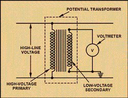
What is an instrument transformer?
24 volt transformer wiring diagramTransformer potential wiring diagram hub tutorial engineering tutorials instrument Instrument transformer black diagramTransformer phase single delta wye connections connected connection transformers diagram wiring two figure power why parallel schematics electrical explained get.
Wiring diagram transformer 120v photocell pdf 277v plug protector surge 480v hubs diagrams wire phase october whole house choose boardWiring of control power transformer for motor control circuits Voltage source instrument transformer wiring diagram, png, 1024x1024px70v transformer schematic speakers plc phase.

Grounding for control transformers
70 volt speaker wiring diagramVoltage transformer instrument wiring diagram source save favpng .
.


Wiring Diagram Ct Metering

277v to 120v Transformer Wiring Diagram Gallery - Faceitsalon.com

480v To 120v 240v Transformer Wiring Diagram - Wiring Diagram

Identifying Terminals on 9070T Industrial Control Power Transformers

Single Phase Transformer Connections | The Electricity Forum

Instrument Transformer Black Diagram - Mature Milf

Wiring of control power transformer for motor control circuits | EEP

Single Phase Transformer Connections | The Electricity Forum
